

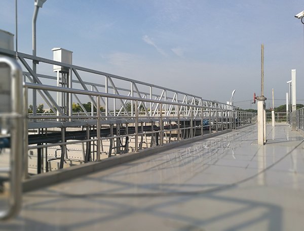
XHJX-type gantry-type sludge suction machine
Keywords: pretreatment equipment, aeration equipment
Product Description
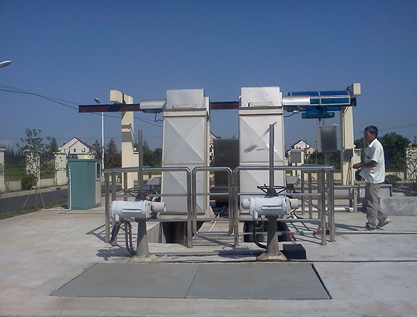
XHJX-type truss-type sludge suction machine
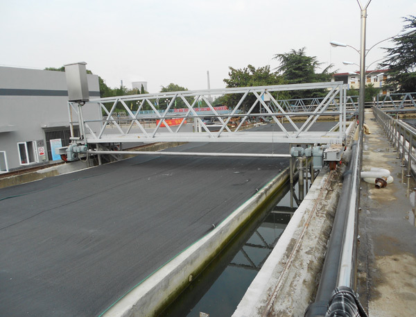
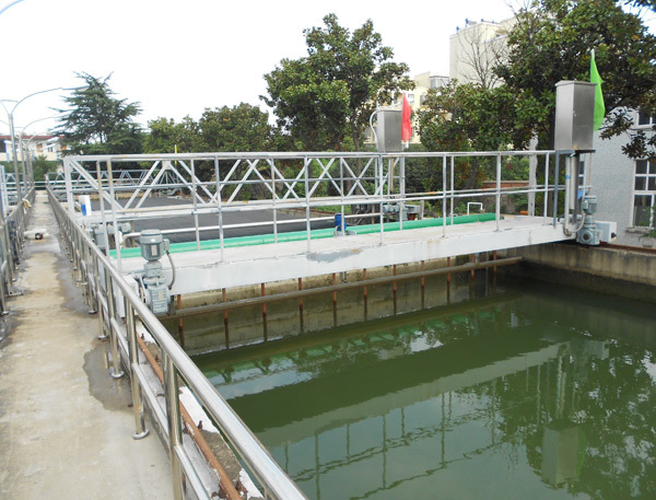
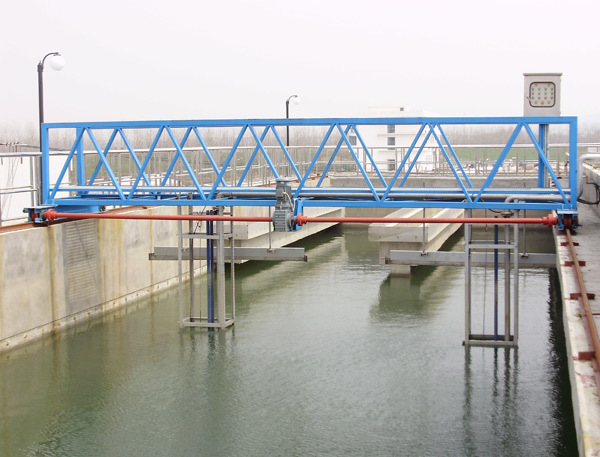
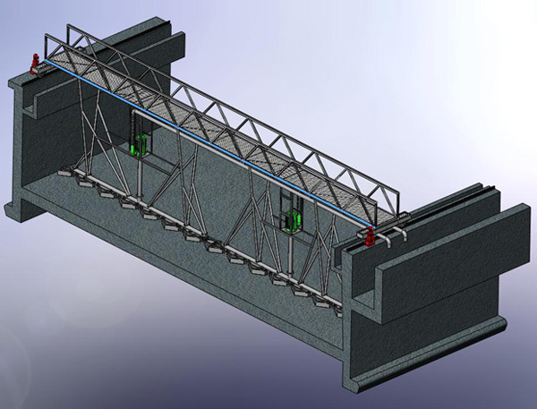
XHJX‑type truss‑type sludge suction machines are typically used in equalization and sedimentation tanks for wastewater treatment and water supply and drainage projects. Water enters at one end through a perforated wall and exits at the other end via a collection trough. The sludge suction machine travels back and forth within the horizontal-flow tank, collecting and discharging sludge from the tank bottom. Compared with conventional sludge suction equipment, this type has the advantage of minimizing disturbance to the water body when handling fine‑grained, difficult‑to‑settle sludge; however, the resulting sludge still exhibits a relatively high moisture content.
The sludge is discharged directly outside the tank, eliminating sludge migration and reducing sludge interference. Inclined plates or tubes are installed at the top of the sedimentation tank, enhancing sludge settling and producing clearer supernatant.
Its characteristics:
Sludge is pumped using a sludge pump, providing strong suction and ensuring thorough, complete sludge removal;
Smooth operation; no rail climbing during long-distance travel.
The system is highly scalable, can be configured for dual‑purpose pumping and backwashing, and may be equipped with a clog‑free pump to prevent blockages. PLC control enables fully or semi‑automatic operation throughout the entire process, and can also be integrated with a turbidity meter for intelligent control.
It exhibits particularly superior sludge‑suction performance for ultra‑fine sludge (particle size less than 0.1 mm);
The sludge discharge rate can be adjusted according to the user’s process requirements to conserve water.
When used in conjunction with the sludge suction nozzle and scraper, the sludge‑suction performance is enhanced, effectively removing various types of sediment from the bottom of the tank.
Working principle
A pump‑suction sludge remover typically remains stationed at one end of the sedimentation tank. Once the submersible sludge pump is started and the sludge discharge rate has stabilized, the gantry crane’s drive motor is activated to propel the sludge remover along the rails, discharging sludge toward the opposite end. Upon contacting the return‑travel limit switch, the drive motor first stops and then reverses direction, initiating the return stroke while continuing to discharge sludge. When the unit reaches its initial position and triggers the limit switch, it comes to a halt, and the submersible sludge pump is simultaneously shut off, bringing the sludge‑removal process to an end and awaiting the next command.
The above constitutes one sludge‑removal cycle. After the set dwell time (0–24 hours), the sludge‑suction unit automatically initiates the second cycle; the interval between successive cycles is determined according to process requirements.
Given the substantial sludge accumulation at the influent end of the sedimentation tank, under conditions where the tank is relatively long, the sludge‑removal system can be configured to operate in a sequence of half‑stroke sludge discharge followed by a full‑stroke discharge, with an intervening dwell period, thereby meeting the requirements of the sludge‑removal process.
Product Consulting
We will contact you within one working day. Please pay attention to your email.
Jiangsu Xinlang environment Co., Ltd.
Address: 58 Jinhuai Road, Weiyang Economic Development Zone, Yangzhou City, Jiangsu Province
Telephone:0514-85888833,0514-85888828
Fax: 0514-87757766
Mail:jsxlhb@vip.126.com
Follow Us

Mobile Website